Showing posts with label CAD. Show all posts

Sunday, 6 October 2013

Tiny Cracks and Pogward Fatness

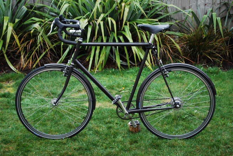
So last Sunday I dressed in my best dapper tweed and went along to the Christchurch City Council Open Streets event (apologies to those without twitface, these are the best set of photos I could find and link to). I decided to take the Pogward along, as my normal tweed bike is still in the depths of my garden shed, behind many other large and difficult to move items. I was going for the mid 20th century randonneur look, so I removed the rack and added the handlebar bag from the Surly onto the seat of the Pogward, a move that worked so well it has stayed there all week.

All went well and it was a rather enjoyable outing, I even met someone who had actually been reading this blog which was amusing.... however during the event I noticed a very slight hairline crack on the top brazed joint of the stem. Clearly this needed sorting, as historically my face doesn't deal very well with impacting the ground from nearly 2 meters up, and I have a pretty robust avoidance policy in these situations.
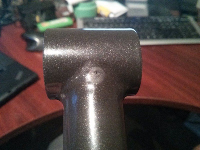
Hard to see the actual crack, but it has obviously propagated from that wee pit

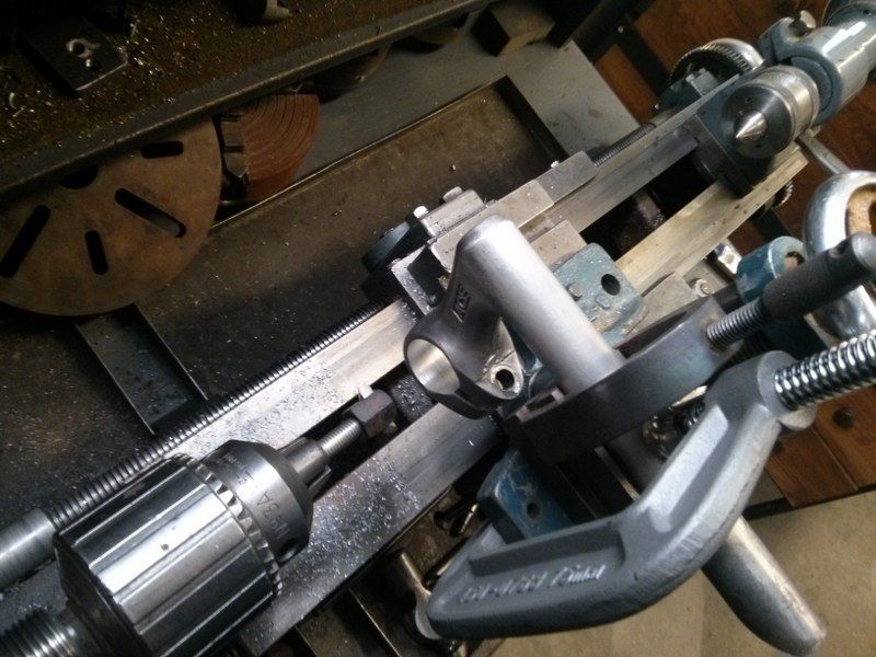
After I gingerly rode home I pulled the stem off and set about finding a temporary replacement until I could sort it further. the only thing I could find in my box of goodies was an old Ace stem with roughly the right geometry, but unfortunately it had a 25.4mm bore, and the VO bars are 26mm. I had a think about how I could sort this out using what kit I had in the garage. Serendipitously I discovered almost immediately that the Grayson has a morse taper in the spindle which means you can mount a drill chuck in there. This meant that I could just possibly pretend that it was a mill not a lathe, and bodge ensued;
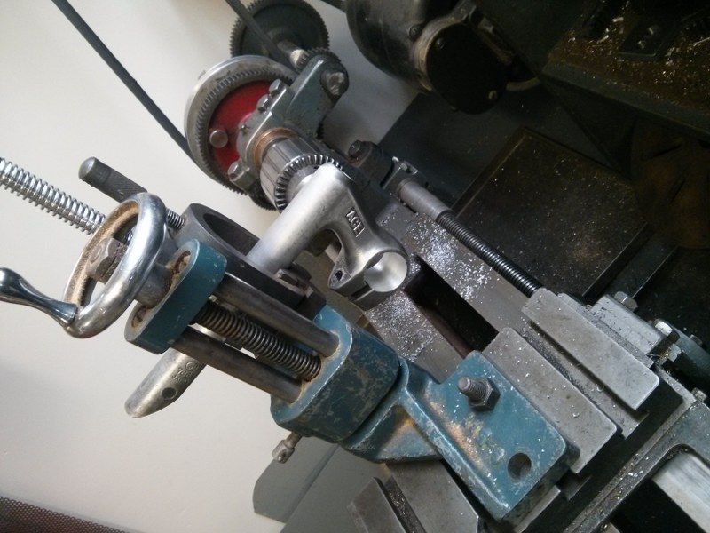
Not pretty or particularly rigid, but it did work
I made a special boring tool for the job from a bolt and a double height nut, incredibly hard to adjust but again, it worked well enough
I had some 1" solid bar that had centerdrill holes in each end, I used this to align the stem bore with the lathe centerline. Things wobbled a bit during the machining process, so I took it very gently. I really must buy myself a mill, I have needed one badly so many times over the last year.

This was all good fun and meant I could actually ride the bike to work again, but clearly this was just a distraction from the real excitement of the week;
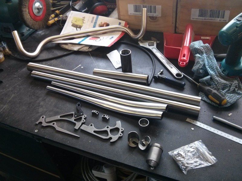
Shiny things, yesterday
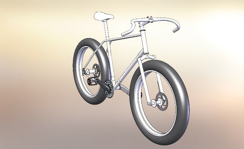
What is that? I hear you asking.... and the answer is; The bits for the next Pogward Frame O' Joy™, which will just possibly look a bit like this;

Mmmm, the fatness of it all.
Yes a Fatbike. I have fancied one of these for a while having ridden a couple previously. The bars are from Tardme, the tubes are from Ceeway and the miscellanea are from Paragon Machine Works. The bars are On-One Midge Offroad Drop Bars, which I got just cos they looked sexy and I thought might look well on a frame such as this. The tubes are oversize mountainbike Columbus Thron tubes, I got those again because I was happy with the robustness vs weight of these tubes on the commuter, stick with what works I say. The Paragon stuff is pretty sweet CNC'd kit and there is the major benefit of having CAD models on the website, which makes modelling a frame in CAD very quick.

The keen eyed amongst you may notice that there are no seat stays or top tube in the parts collection, this because the design harks back to a BMX I had when I was 12 or so which had twin top tubes all the way from the head tube back to the dropouts. This bike was fully chromed and the envy of all who spied it, at least in my mind it was... If I can capture a wee bit of that misty eyed goodness in this frame then I will have succeeded. The tube for that and the forks is currently on order from Lianne, I should see it in the next couple of weeks.

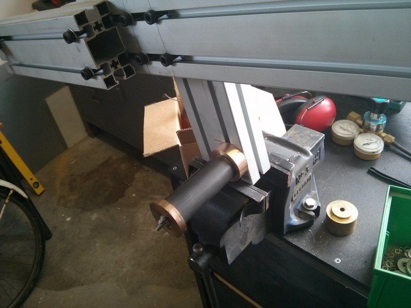
So this weekend was given over to modifying the frame jig to suit the new geometry. This is where noob assumptions have caught me out - I never imagined I would be making a frame with a 100mm wide bottom bracket, a 170mm rear dropout spacing, a 135mm front spacing, a 1-1/8th threadless steerer or even a frame with different head tube/seat tube angles. I spent considerable time drilling and filing things to get the jig to fit the geometry, then started to sort out the mounting points;
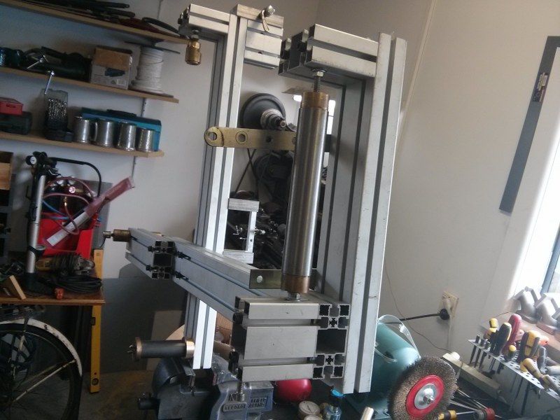
The headtube and seat stay just needed the top mounts slipping down a tad
Bottom Bracket mounting needed a new inner mount to get the correct spacing
Next up will be the axle spacing, this will probably be addon bits rather than reworking the whole thing, I just need a couple more taps to do this. After that is the fork jig, a bit more of a serious effort will be needed here unfortunately. Maybe I will make a whole new jig to keep it easier to handle, I am not sure yet.

So the frame will either be Tig welded or fillet brazed, I haven't yet decided that either.... I have just bought a new welder that is a combo Mig/Tig, but the Tig function is pretty unsophisticated compared to some machines I have used in the past, so requiring a wee bit of skill to get a sweet joint. Balancing this is my slightly increased fear of fillet joints cracking, a recent experience of which has tainted things a bit. Fillet brazing is probably going to be the way though, I shall just pay a lot more attention. The forks I definitely will Tig, the many kilograms worth of Chumly they will see has already decided that....

A lot to think about then, and much more to discuss - gears, wheelsets, brakes etc....

Saturday, 10 August 2013

The Pogward Resplendent

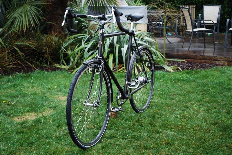
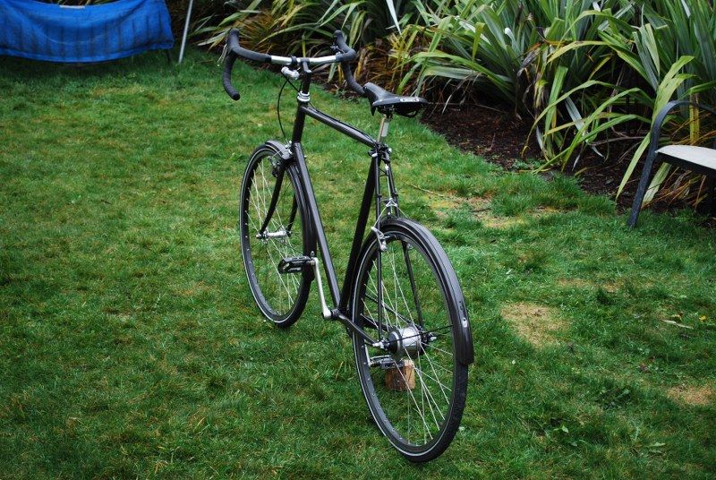
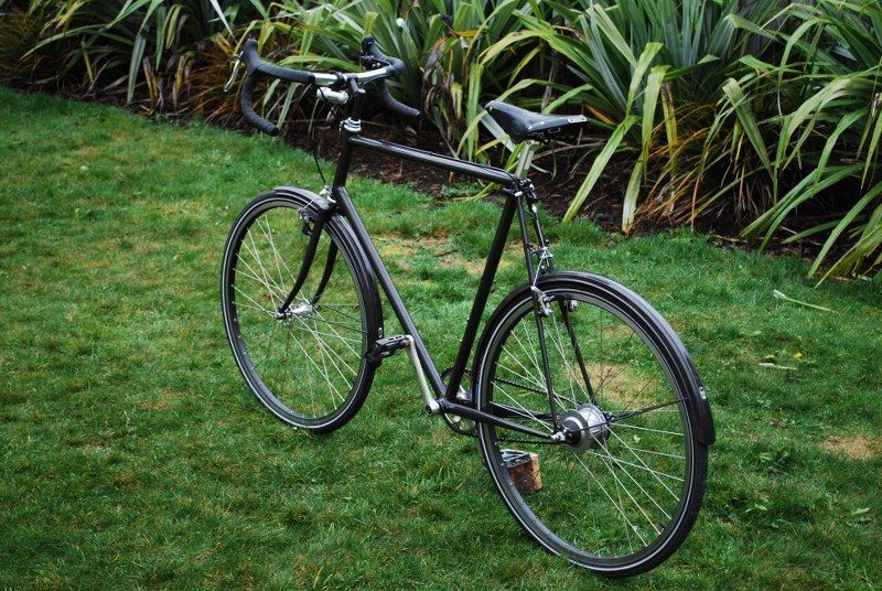
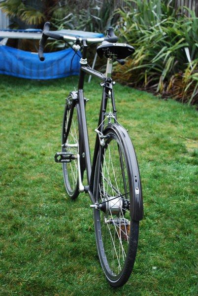
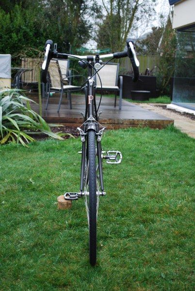
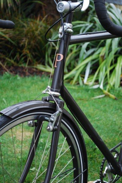
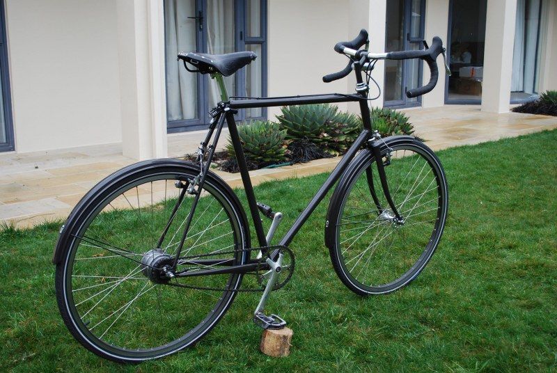
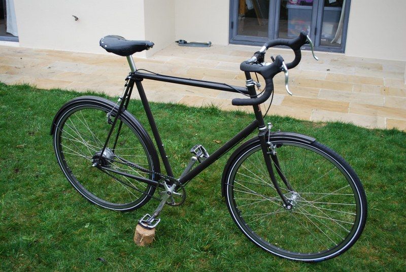
Well what can I say, this thing is probably as finished as it will ever be now, short of some different brakes if I can find anything suitable, and just possibly dismantling the rear hub and polishing the housing so the finish matches the front hub - this might be excessively anal though. I have discovered some latent OCD in the last few months, so who knows.

I treated the beast to a new set of Shwalbe Marathon Plus tyres, as the rear tyre was pretty cut up and bald, and as a finishing touch made a copper headbadge.

This will not be the end of the blog I imagine, I found myself laying out the geometry for a new frame in Solidworks this morning, something quite different than this... parts may be ordered soon.

Anyway, lets let the pics tell the story.


Friday, 29 June 2012

A dropout rethink methinks

The dropouts have been preying on my mind while I have been busy sorting out the Gazelle the last week or so. I was never 100% happy with the tensioner adjustment being below the chainstay, I imagined careless parking would probably bend the screw, plus the design did not have the simple elegance that I look for when designing things - and when you get that, you know you probably have it right. A comment from philthy on my last post got me thinking about the durability of the dropout material, and that I should probably have made them from proper CroMo to match the rest of the frame, or at least faced the dropouts with stainless steel. Either way this meant I had probably wasted some time machining up those new ones.

However in my opinion, wasting time getting things wrong is the prime causes' way of preparing you to eventually get it right, so I have decided to have another go...

The initial design with the standard dropouts was going to require some tweaking of the bottom bracket chainstay angles to get the fit right, and once I set the new dropouts up in the jig it was pretty obvious that getting a few degrees off center angle on the chainstays was not going to be a problem.

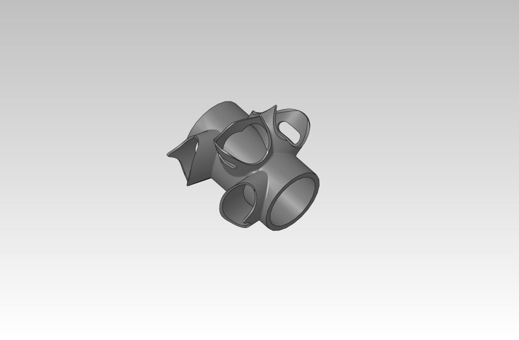
So last night I sat down for a CAD session at the computer (my wife was gallivanting around the frankly scary pub selection in Addington with her Plunket/coffee/wine/AA group, and I was 'babysitting'), and assisted with my own suitable brain lubrication I smashed this out;


This design has the benefit of the adjustment being inside the frame, plus there are less curves and angles, making it more pleasing to the eye in my opinion. The only real issue is the adjustment screw taking a significant amount of meat away from the connection between the chainstay and the seatstay, but I can always beef this up some more, we will see. I call this design the frogmouth MkII, for obvious reasons.

Now I need to source some 8mm 4130 steel, and get to cutting...

I have been thinking hard about the brakes for this bike, initially I was intending to put standard MTB brakes. this would be ok but maybe not that pretty, I think that these might be a better option;


They are nice, if a little bit hard to get hold of in NZ.

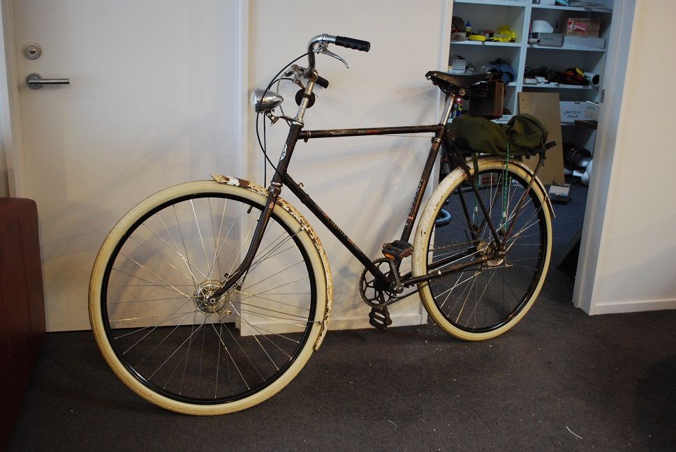
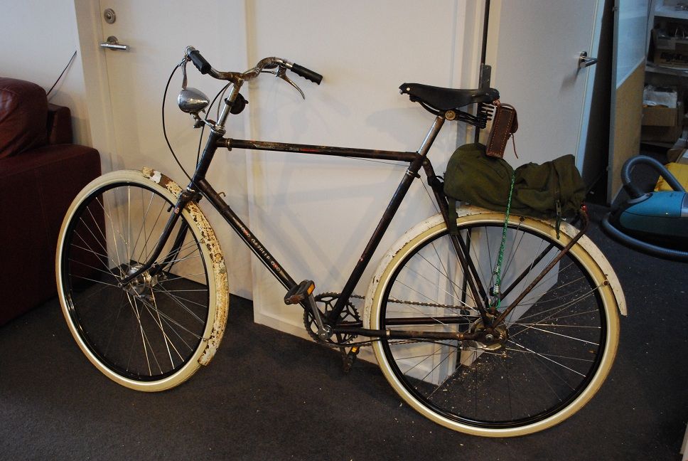
The Gazelle has continued as it started, ie being extremely truculent no matter what I try to achieve with it, however the journey is fast drawing to a close. So close in fact that I foolishly decided to ride it to work yesterday. There were a few teething troubles (I needed to stop at least 4 times to adjust the gears, tweak the guards, clean my undies after trying to stop in traffic). I did however get a scalp on my ride home, but this was simply because I had maxed my FCN, so everything on 2 wheels was fair game.

Still it was fun, and I took a couple of pics to mark the occasion;


Those wheels where very time consuming, I bolloxed it up the first time not realising that the spoke holes were offset, plus I got the lacing wrong, plus the rims turned out to have larger than standard nipple holes, plus the spoke lengths were not quite right, etc etc... Dave very kindly sorted things out for me though, he is a solid chap.

I still need to shorten the brake lever arm at the front to make the brakes actually perform their function, and maybe find a new gear cable. And probably sort out a chain guard. And maybe find a pannier for it. Apart from that I think it is looking pretty swish and rather gentlemanly, don't you think?

Sunday, 27 May 2012

Framejig Ahoy, and bonus Gazelle of Doom...

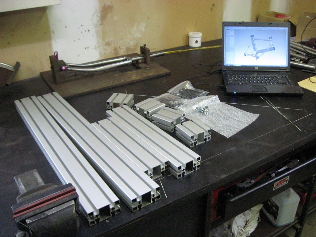
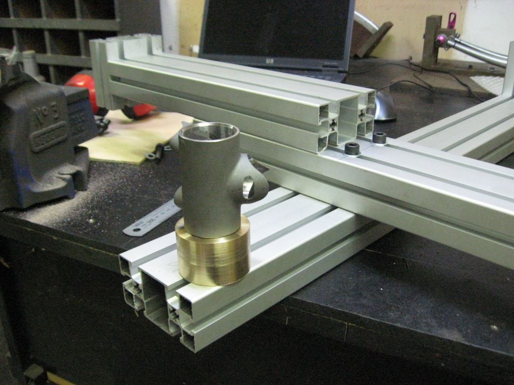
Mmmmm, Minitec


Now to make it look like that thing up there on the laptop...


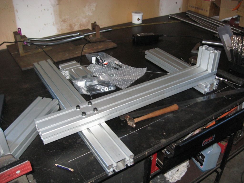
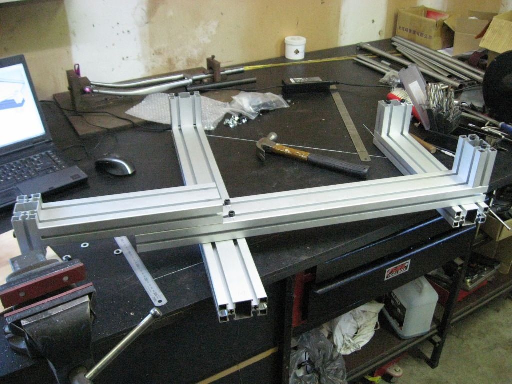
Sweet. This is already one brazillion times better than the steel jig effort, stiff as a schoolboy with his first stick mag.

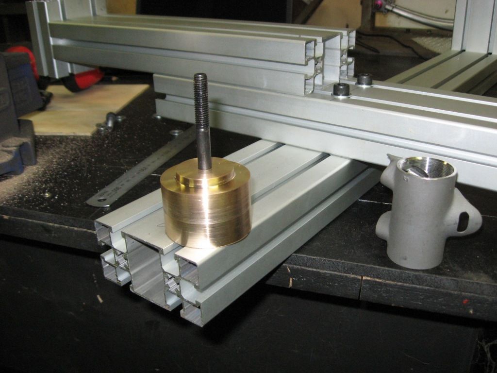
Now to  justify the massive expense of that lathe, this will account for one one half of a percent I would guess;


And that is pretty much where it sits right now, having well and truly used up any spousal goodwill I may have scraped together this week... this is mostly because the Gazelle finally arrived and I spend an extraordinary amount of time getting it to the rideable stage, but still nowhere near finished;


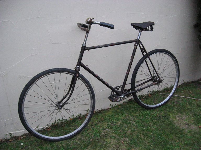
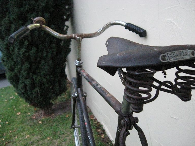
The pics do not do justice to the sheer size or ridiculous rake this thing has.

Everything was against me on this thing, every bolt was rusted up or broken off, and the sweet drum brake wheels are going to need re rimming which is why it has a spare set of 28"s on it for now. The rims actually turned out to be 700c, not the end of the world as I had a set of 700x45 tyres lying around. I thought I would chuck them on despite the poor condition of the rims, just to get it up and running, however one went bang before I even got it onto the bike...

The 700c rims are because it was actually built in 1977, so is a really quite irritating mix of old school design and newish school parts, ie the cotter crank axle was a Thompson type with pressed in shells. Of course I managed to smash one of the cones trying to remove one of the crankarms, rendering the entire crank useless. I then had to machine down a threaded bottom bracket shell and press the whole thing in. It worked well, but what a rigmarole.

On the positive side, the drum brakes were in good condition once cleaned up, and the Sturmey Archer 3 Speed was in perfect condition. A stripdown, clean and reassembly was all that was required there.

To ride it is very spacious and comfortable, and with a set of guards and various other accoutrements it will serve me well as my future Tweed Steed.

Sunday, 13 May 2012

Jiggy wit it

The jig is proving somewhat problematic...

Not being the sort of man to spunk actual cash on the real thing when I can get a reasonably functional facsimile by doing it myself, I am going to build my own jig to hold framey things in place. My first idea was to make something up out of bits of not too heavy structural steel - I already own a MIG welder and so throwing something together should be a doddle. To this end I purchased a length of second hand 80x40mm channel (probably the start of my failure right there as it looked as though it had been salvaged from a beach somewhere, and prior to that had been coated with some form of rust preventative substance that could only have been sourced from a 1980's Italian car factory). Adding to my woes was that the channel web was not very flat at all, in fact 'ribbed for pleasure' was the phrase that came to mind. Certainly good for preventing conception anyway, I should have got wood.

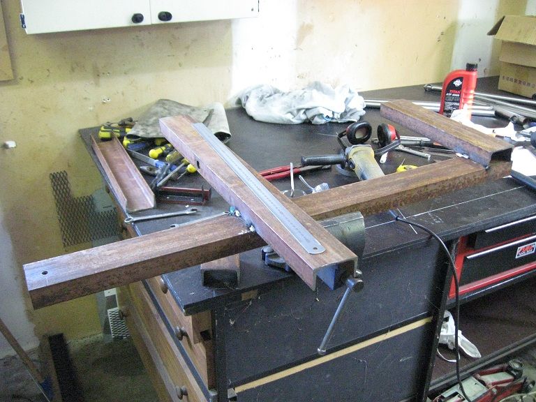
An hour or so on Saturday morning was spent creating this;


As soon as I started marking out the centerlines of the frame and such, it became immediately apparent that this just wasn't going to be good enough, a finger push was enough to twist the frame a few mm out of whack. I could brace everything with more steel but it is already a heavy little bugger. This, coupled with the actual impossibility of getting the bits even roughly flat to each other in the first place due the built in Mariana trench on the steel meant I needed to come up with something better.

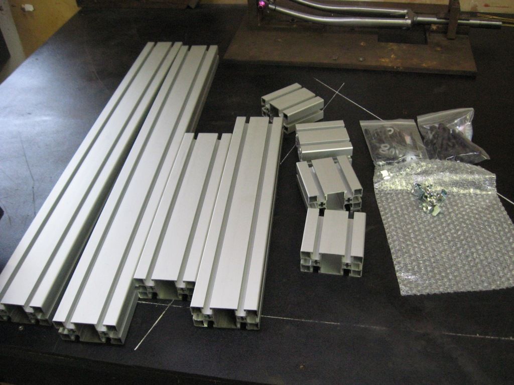
Now, I have recently designed a test rig for one of the local tech companies and the basic frame of the rig was made out of stuff called Minitec. Using this can get kind of expensive but it is an extremely flexible way of building framework for things - proper jigs commonly use very similar stuff, although it is usually their own custom profile.

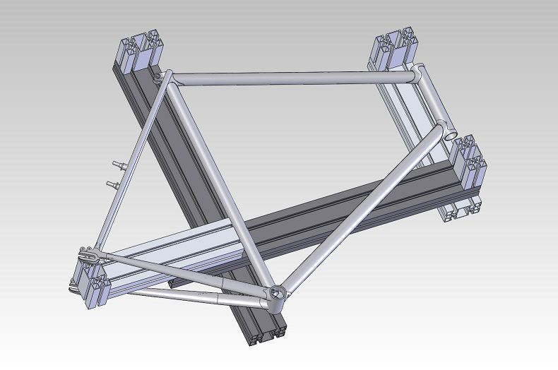
Sod the cost I said to myself, it is clearly the way forward... and in a trice I had come up with this;


Actually I came up with something very similar to that pic, but then I found this, which caused some tweaking to take place. Sincerest form of flattery and all that...

Anyways, tomorrow I will get a quote from the local supplier for the bits that I need, and assuming I need not sell a kidney to pay for it I think this will be the way forward. It certainly simplifies manufacture of the other bits that actually hold the frame, so we shall see.

In other news, these last few weeks I have been pondering using a Gates belt drive with the Alfine when it gets put into the frame. This makes a lot of sense, particularly after a blowout I had a week or so ago, the fixing of which left my hands looking like I had lost a contact lens while inspecting the inside of an oil tanker. This episode eventually resulted in some quite fetching Ramboesque face camo so not all bad really.

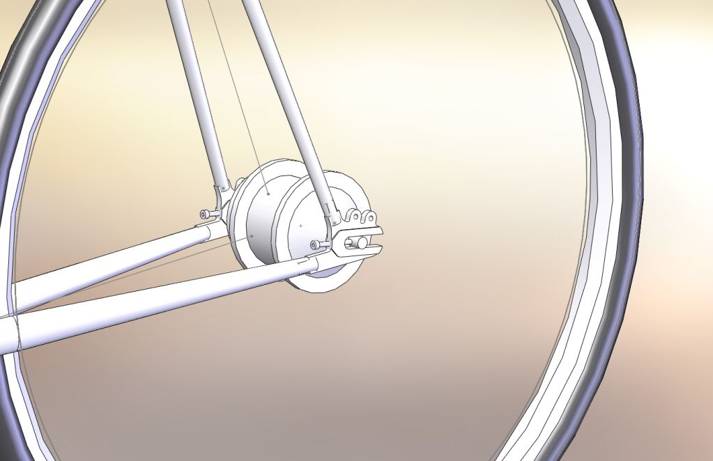
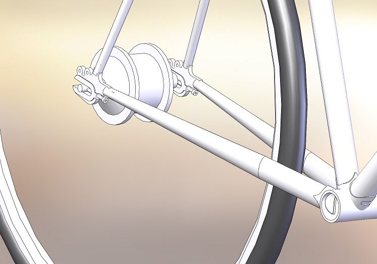
There is no need to lubricate the belts on the Gates system so it would be much nicer to handle...but the issue is that the belts cannot be split like a chain, and so you need to have a way of splitting the rear triangle to fit it all in. There are a few ways of doing this but the least invasive is to put a joint in the seat stay like so, and this is probably what I will be doing. I may put this in anyway so I can go down the belt drive path later even if I don't now...

All of this has caused me to rethink the dropouts - for a start you need a pretty robust tensioning method for the belt which isn't that easy to get with the dropouts I ordered, plus it turned out that the angles on these dropouts are a fair way off optimal for my geometry. This could all be dealt with without too much issue, but I thought it would be nice to make up something proper for the task. I am not 100% happy with the design yet but I will first see what the manufacturing cost comes in at with this version that I have had quoted. I can always make them from scratch anyway as they are not too complicated...


Monday, 30 April 2012

The engineer in me bursts forth

So in real life I am an engineer, which suits me down to the ground as I can still earn a reasonable living while adhering to minimum dress code. In practice this means as long as my genitalia are not visible things are considered mostly satisfactory. I have been an engineer since the age of 4, and my Mother can probably pinpoint the very hour it happened because that is when I was given my first lego set. Within minutes I had constructed a reasonable facsimile of a car and was performing rudimentary stress analysis against doorframes and walls. Like most of my hobbies, it just snowballed from there.

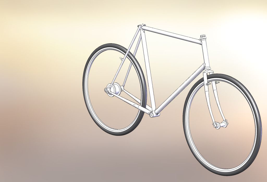
Now one of the benefits of being an engineer is you get some pretty sweet tools, and one of the most useful for the sort of thing I do is 3D CAD modelling. This allows me to generate pretty things like this;


In fact I have modelled pretty accurately* all of the lugs and tubes that have arrived. This is fab all in all, as it takes a significant amount of guesswork out of the design process, plus lets me know if any of the parts I bought from Ceeway are not suitable. As it turned out my seat tube is marginally too short for the geometry I want, but not enough to cause serious issues.

Real framebuilders will scoff and snort and say 'damnable newfangled nonsense, when I were a boy we had nowt but sticks and the grime from our own foreheads to create our geometrics sonny boy!' Well yes, but if it means that I am one step closer to making a frame that is actually useful, having put so much time and energy into it, then so be it...

* See post #1, the engineers cry; 'Close enough is good enough'